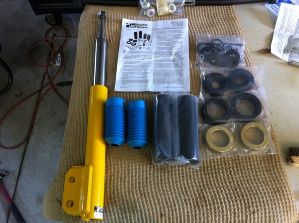
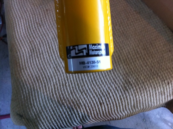
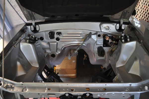
The car has been apart for quite a while. Now that the engine bay paint is completed, I can move on to the Maximum Motorsports Max Grip Box installation.
The MM instructions are pretty good. They start out assuming that your car is still together and driving. Mine was stripped down with no front suspension in sight…so I skipped the first 3-4 pages.
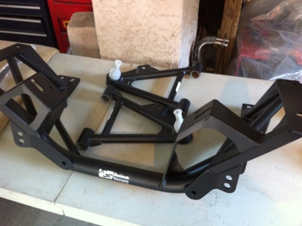
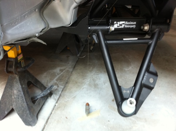
When you’re doing the entire suspension, you can almost start anywhere. I decided to assemble the K-member / Control Arms first and then square them up to the chassis.
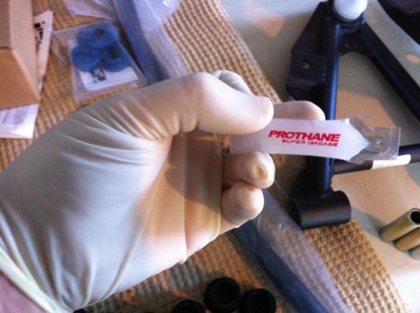
Basically, you’re going to bolt the control arms to the k-member. When assembling the bushings and sleeves into the control arms, a VERY thick grease is applied. Get a box of gloves and change them frequently unless you want EVERYTHING you touch to be graced with a sticky, dirt attracting coat of grease. It’s like normal grease and superglue had kids – no kidding!
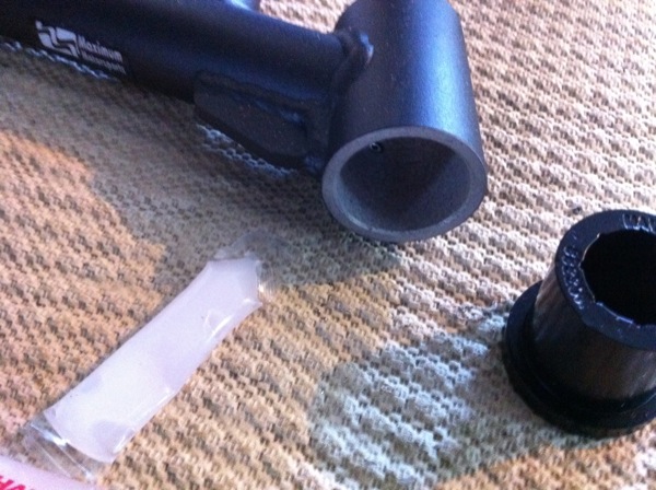
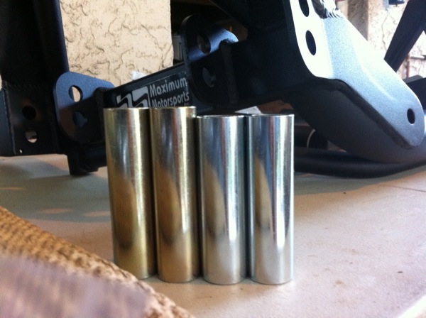
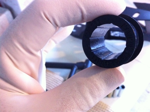
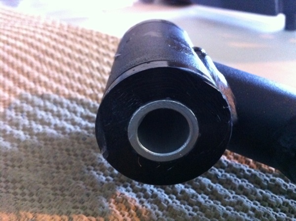
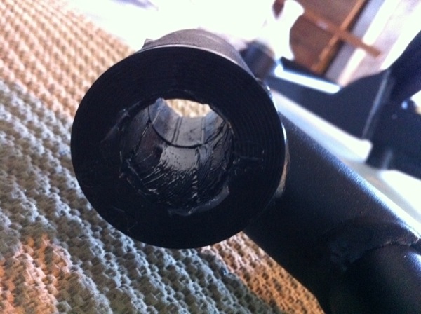
Here you can see the poly bushings that are inserted into the control arms – they go in both sides, 4 per control arm. Grease everything up first. You can see the ID of the poly bushing is grooved to hold and distribute grease. Grease the sides too, where they will contact the k-member. The steel sleeves are inserted into the bushing assembly prior to installing the control arm into the k-member. Watch out because they are different lengths, front and rear.
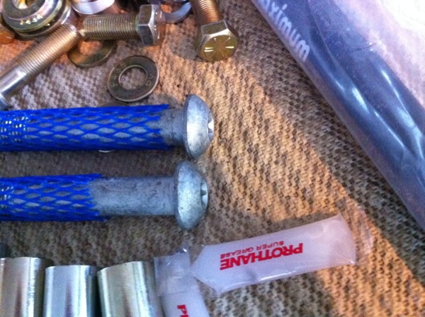
MM now includes these low-profile front control arm bolts to replace the factory ones where the larger head would previously contact the power steering rack boots. You must use the factory rear bolt and both factory nuts. MM includes two nuts that DO fit but they are spindle nuts, so don’t use them here.
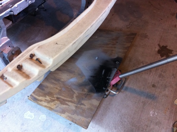
My favorite way to install a k-member by myself. Just jack it up and bolt it in.
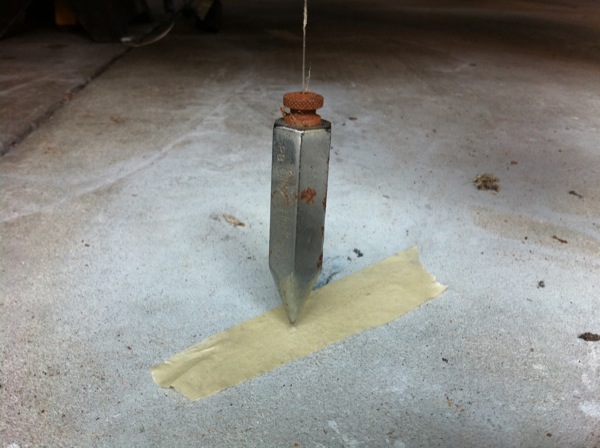
To square the k-member into the car, do the following:
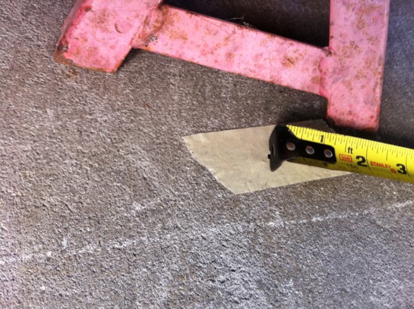
- Use a plumb bob at four points around the car and mark those locations on a piece of tape on the floor below. The k-member has two holes for the front corners and use the outside of the chassis bolts on the rear control arms.
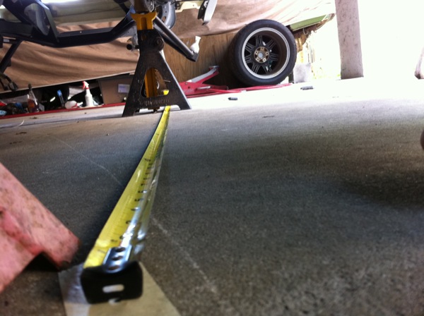
- Measure front to back on each side and move the k-member until this is equal.
- Re-mark the front locations with the plumb bob, as they will have changed. Measure the diagonal corners to set the k-member side-to-side location.
- When you think you are done, measure again.
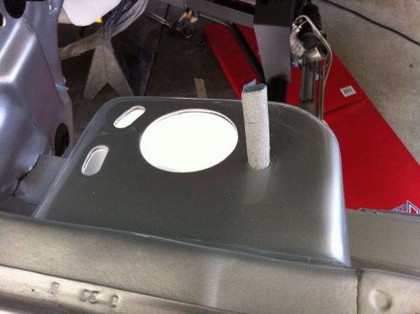
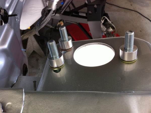
The caster camber plates are painfully easy to install. You should be able to tell how they go together from these pictures. I didn’t have to use the bump stops that are included with the kit because the MM struts that I have include internal bump stops. The only problem that I had was a little excess filler in the holes at the top of the shock towers. I couldn’t really see it, but it was there and it stopped the plates from reaching their full range of adjustment. I had to sand a couple of the holes to make it all fit.
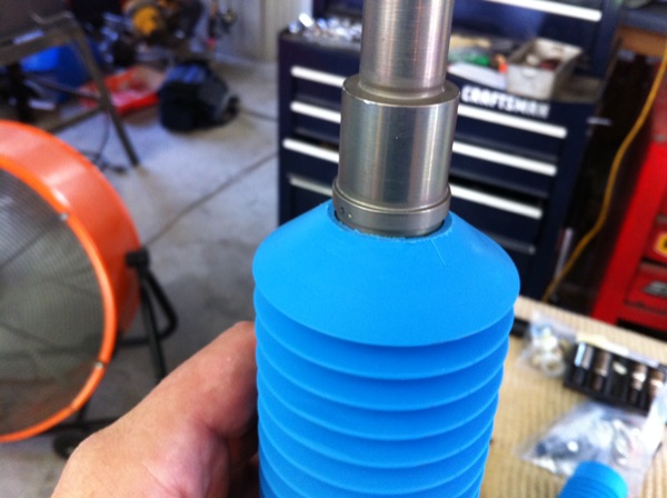
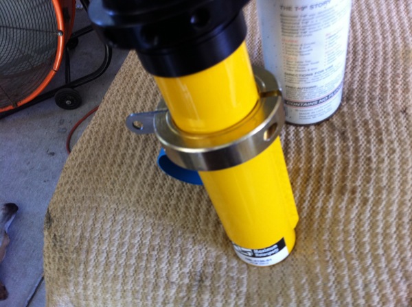
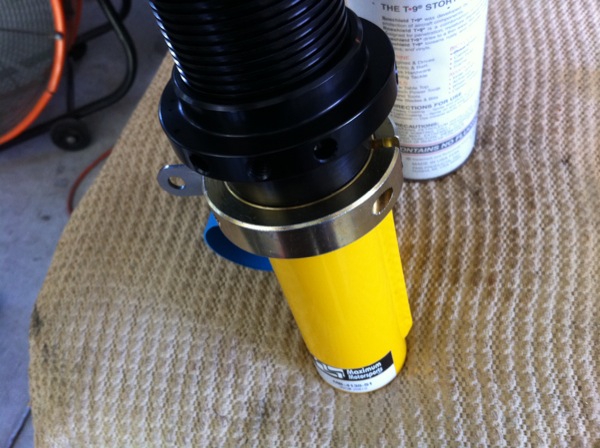
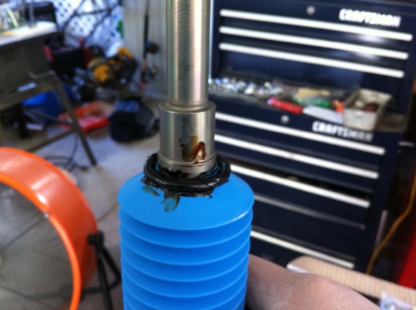
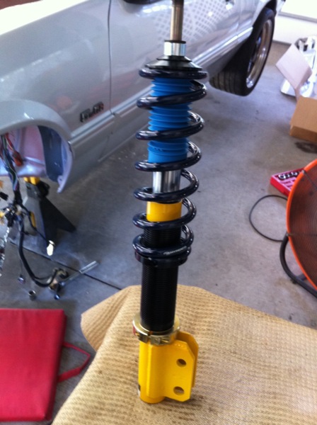
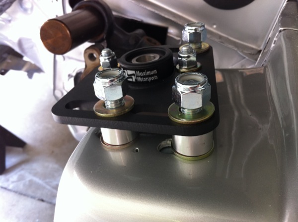
The coil-overs were pretty easy to assemble. I didn’t get a picture of the bearing at the top of the assembly. I just didn’t think about grabbing the camera while my fingers had wheel bearing grease on them. It’s basically a flat thrust bearing inside two flat races (they look like washers).
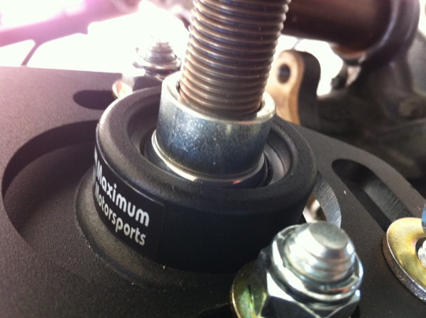
Following the MM instructions, I installed the correct spacer onto the coil-over assembly and then installed it into the caster camber plate. It’s likely that you’ll need a spacer on the top as well to avoid running out of threads on the strut.
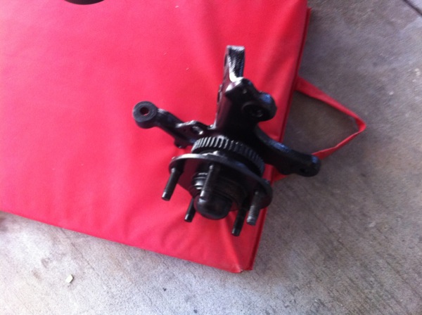
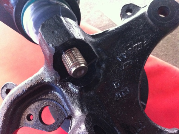
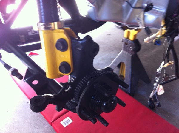
I cleaned up my old spindles and installed them onto the lower control arm ball joint. I was happy to see that this ball joint did not require the spacer usually needed when using SN95 spindles on a fox ball joint.
Almost ready to order the 5.0 Crate Motor.
